 |
| home | about | making of | videos | faq | contact |
 |
|


At this point we knew this scene would take many hours to shoot. It was decided to move all the
gear to Steve's garage, as it was a space that could be easily controlled for lighting, and would
not be disturbed. We bought some cheap 1KW workshop lights to light the room, bouncing the beams
off the ceiling for the neutral soft shadowing that the scene required.
| |
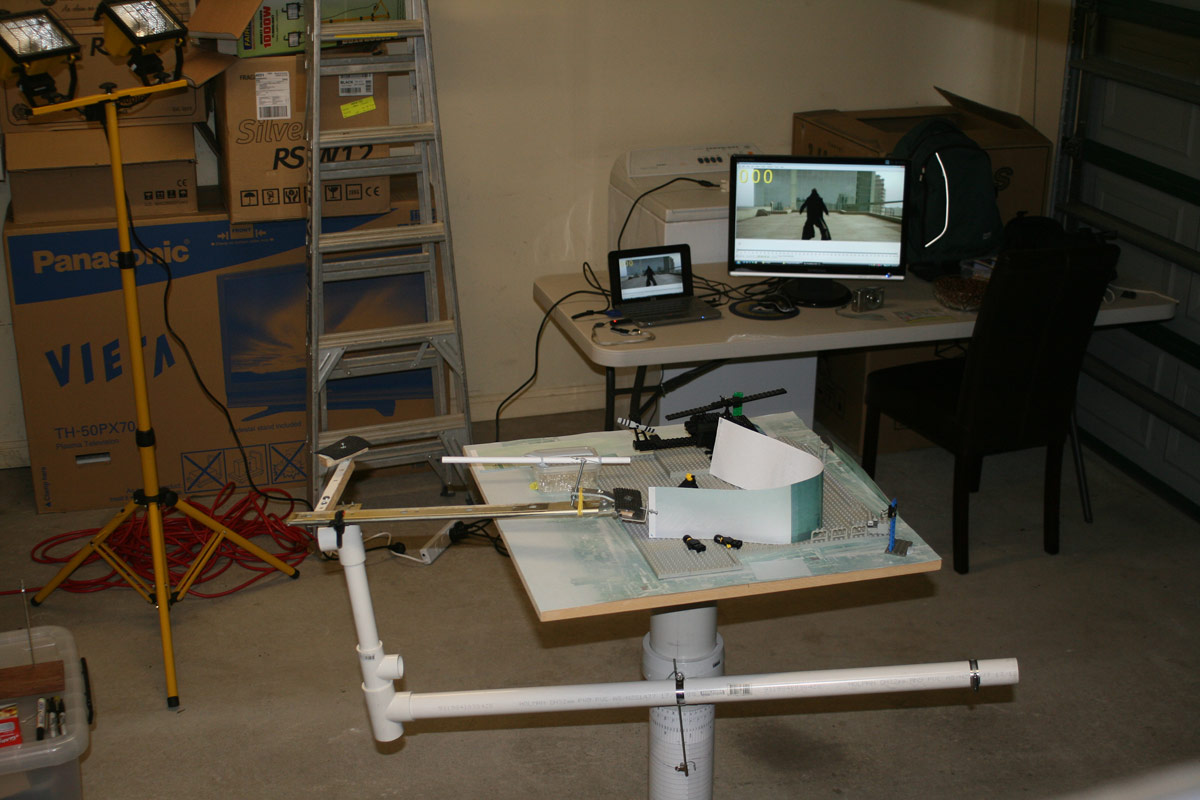 |
Here is the gear in Steve's garage. On the left is one of the workshop lights we used, pointed upwards to bounce the light off the white ceiling. This gave us the soft lighting that was needed for this scene. At the bottom is the OCR, but without the cameras mounted or the set in place just yet. At the back you can see a HP netbook and external monitor showing the original video frames. We used this to not only see what the current scene was, but to also step forward and backwards through the video to see how the animation progressed. This was invaluable, as often the differences between frames was almost invisible, and you needed to know where it was all heading. |
Speaking of stepping through the video, we used VirtualDub
for this. Trevor also wrote a custom filter that could display the frame number (amongst other
things like the timecode) in any font, colour or position. We also used this filter to place a
crosshair in the centre of the frame, so we knew exactly where the camera should be looking. There's also a giant bowl of chocolate sultanas there. For a shot of this magnitude, we needed all the chocolate boost we could get. Before the final filming began, we needed to spend ages getting the angles and suspension systems worked out, as well as where the camera had to be at key points in the animation. The height, dolly (in and out) and tilt of the camera was noted at these key points, and then the intervening values calculated from that. Because of the OCR, this is the only shot we did where we knew where the camera had to be at every frame. It was just too complex a scene to do it in our usual way, which was "I'll move his arm a little bit in order to get it all the way by the end of the scene." | |
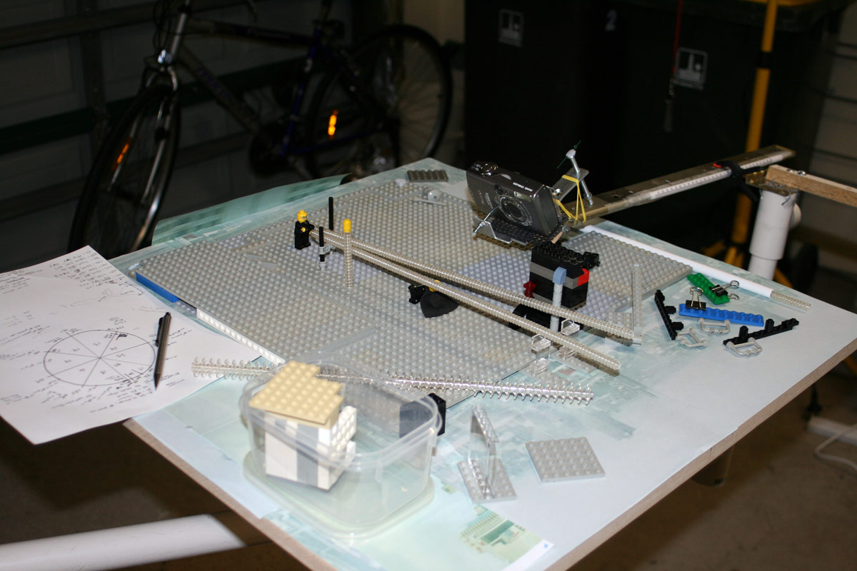 |
Here you can see one of our test shots to see where we could put supports in
for the bullet trails. They could only be made so long before the agent could
no longer hold them without sagging, and with the camera moving around we had
to be mindful of which end we could support them from. The clear column with
the yellow bullet on top was a position marker for where the edge of the visible
frame was. We were often amazed at what it was exactly that the camera could
NOT see. You can also see a new mount on the front of the camera with a screw running through it. This was a jig Trevor made in an effort to fix the camera in place rotationally around the screw that mounted it to the main arm. We needed this so we could re-align the camera when we had to disconnect it to replace the battery. |
On the left of that photo you can also see our important "frames of interest" drawing. The circle
represents the full spin of the camera for this scene, and it is divided into eighths with frame
counts and bullet-trail in/out points noted on it. Lists down the bottom also show height/dolly/tilt
values for key points. Once these were finalised they were transferred to an Excel spreadsheet so
we could easily create the "between" values for every single frame. This then gave us a detailed
running sheet for the entire shot, with camera values for every frame.
| |
 |
Here's a test we did for the tricky part where the camera has to pass through
the bullet trails. Obviously we couldn't do this in the same way they could
do it with computer graphics in the original film. For ours, we decided we
could smoothly raise and lower the trails out of the way, allowing the camera
to pass by. We had to do a lot of tests to see where to start and stop this
process, and to see if we could even get away with it. It wasn't a perfect
solution visually, but we really couldn't think of a better way. We had to be careful where the thread was tied onto the trails so the camera couldn't see them, and we pulled it off fairly well. You can just make it out in our movie if you know what to look for, but it is in no way obvious. |
The trails were suspended from some square aluminium tube with screw holes tapped into them for
the threaded rods to run up and down through. These were mounted to our gantry, and if you look
closely on the far right you can see that one of the support arms has been raised to allow the
camera to pass by it. These supports slotted into holes in the base of the set, and wing nuts
tightened them down.
| |
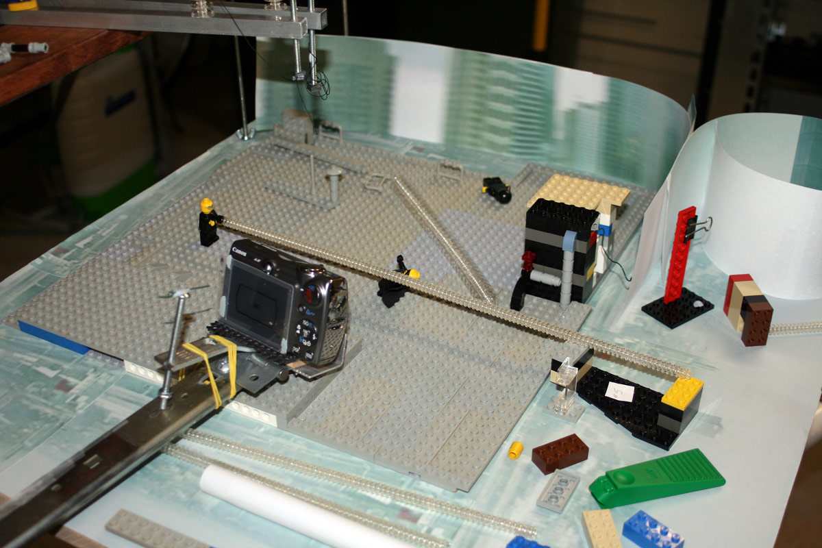 |
This was some more planning of camera angles and heights. You may also notice a green
wire hanging off the back of the building with the pipes there on the right. It was
used as a support for a bullet trail that came past the pipes on that building. Another
trail used a clear window as a support (which can be seen at the bottom of the shot),
and you can make it out in our finished movie if you know where to look. We had to use supports that were as invisible as possible as they would be in view of the camera. The Lego construction at the bottom right (with a paper #5 on it) was one of several height guides we used for various bullet-trails, when they couldn't be seen by the camera. |
The Lego fanatics out there might realise that the type of gun the Agent is holding ends in a hole,
and not a stud, but the bullet and trail are still stud forward. The black connector piece between
the gun and the trail is the small circular piece cut off a common 1x1 block with circular holder
(Lego call it a lamp holder, design ID: 4081). The leftover 1x1 plate is still usable if you are
careful with your trimming.
| |
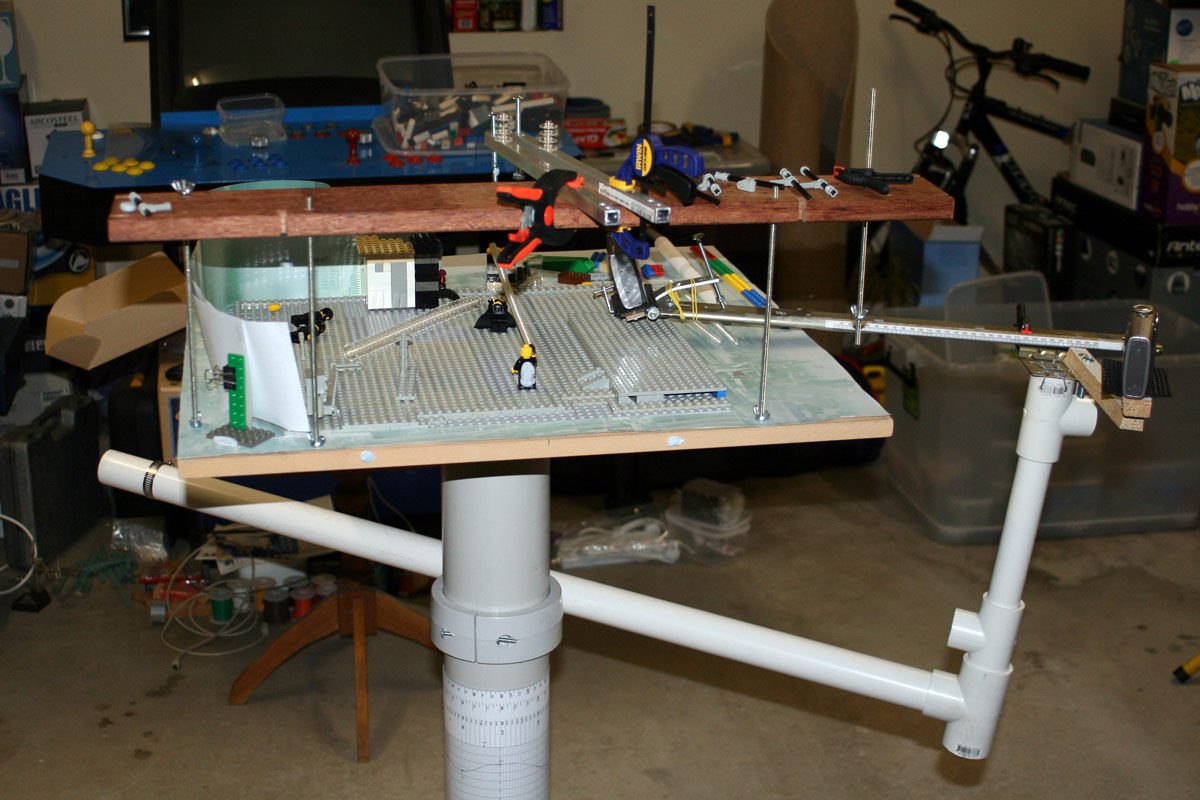 |
Here you can see the gantry and how it sits on the set. The last support arm on
the right is raised so that the camera can swing past. You can also see the Blu-Tack
"parachute" that we stuck on the back of the agent. We had glued his arm into
position to better hold the weight of the bullet-trail, but we needed to strengthen
his waist without locking it into one position. This worked well enough. At the bottom you can see the height/frame guide on the OCR support column. The curving line shows the change in height of the camera for any given frame number. Steve also needs to get that arcade machine in the background working properly. He's put that off for far too long already. |
 |
In this shot you can see the paper guide tubes we used for some of the trails.
These were aligned with where we wanted the bullet trail to go, and afixed in
place with Lego stands. We could then use these to both sight down, making sure
the agent was firing the bullet in the correct direction, and once long enough
the trail could be slid through the tube, ensuring that it was removed from the
scene in a smooth straight line. Worked great so long as the camera was never
in a position to either see the guide, or get in its way. At this point it was 8pm, and we were taking a dinner break. |
From this point on, it was just laborious shooting of frames. We had all the technical aspects
worked out to some degree, so there weren't too many surprises left in store for us. That's not to say it didn't take us forever. The first frame was shot at 1:30pm on Sunday afternoon, and the last shot at 4:15am Monday morning. The following day at work was horrible, let me tell you. | |